


Physical and Remote Kill Switches
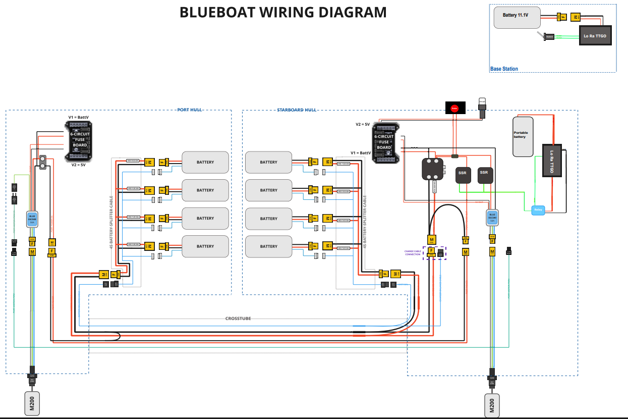
Both kill switches act on the power supply of the BlueBoat's actuators. The physical e-stop consists of a normally closed, manually resettable switch with a red button accessible on the starboard side, through which power passes before reaching the propulsion branch relays. When triggered, it opens the power line to the thrusters. The remote kill switch adds two normally open solid-state relays on that same branch, controlled by a LoRa receiver unit that opens the relays upon receiving a stop command or after two seconds without a signal. Both mechanisms are integrated into the same power path, so the actuators are only enabled when both the physical switch and the remote relays are closed. Control electronics are powered through a separate path to preserve status indication after a cutoff. The design rationale behind this arrangement is to cut propulsion through two independent means in series while keeping the control power supply active for logging and displaying the kill-switch status. As a pending item, the water cannon's e-stop will be integrated into this same line via a relay, given that it operates on an external battery and will be handled in a similar manner.
Status Light
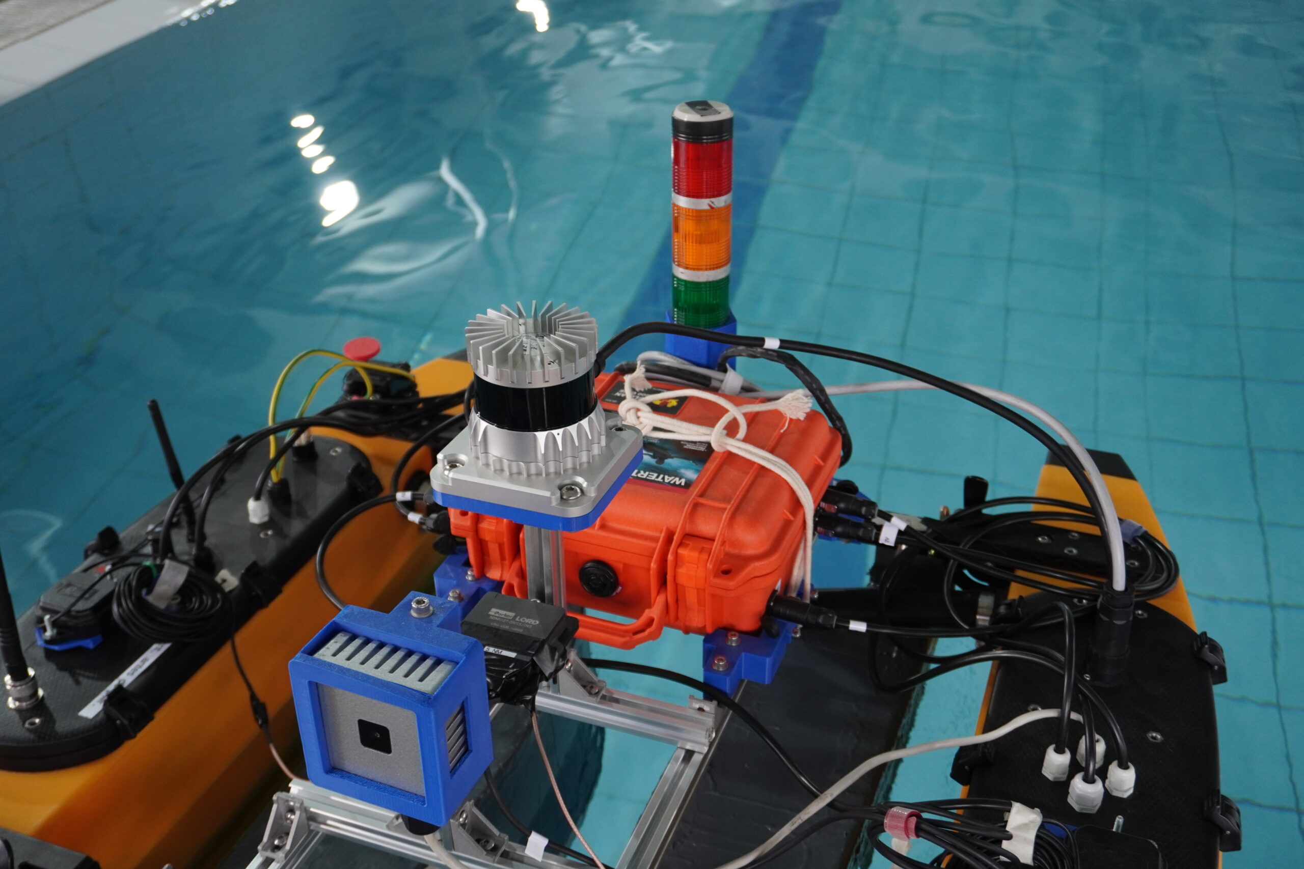
The status light serves as the visible indicator of the ASV's state, located on the starboard float and connected to the 24V terminal block. When an emergency stop is triggered, the indication turns red, which is why the electronics responsible for determining and communicating the system state remain powered even when the actuator branch is cut. Powering the indicator from the distribution branch that stays active during a stop ensures the stopped state remains visible at all times. Red indicates an actuator stop, yellow indicates manual mode, and green indicates autonomous mode.
Power Distribution System
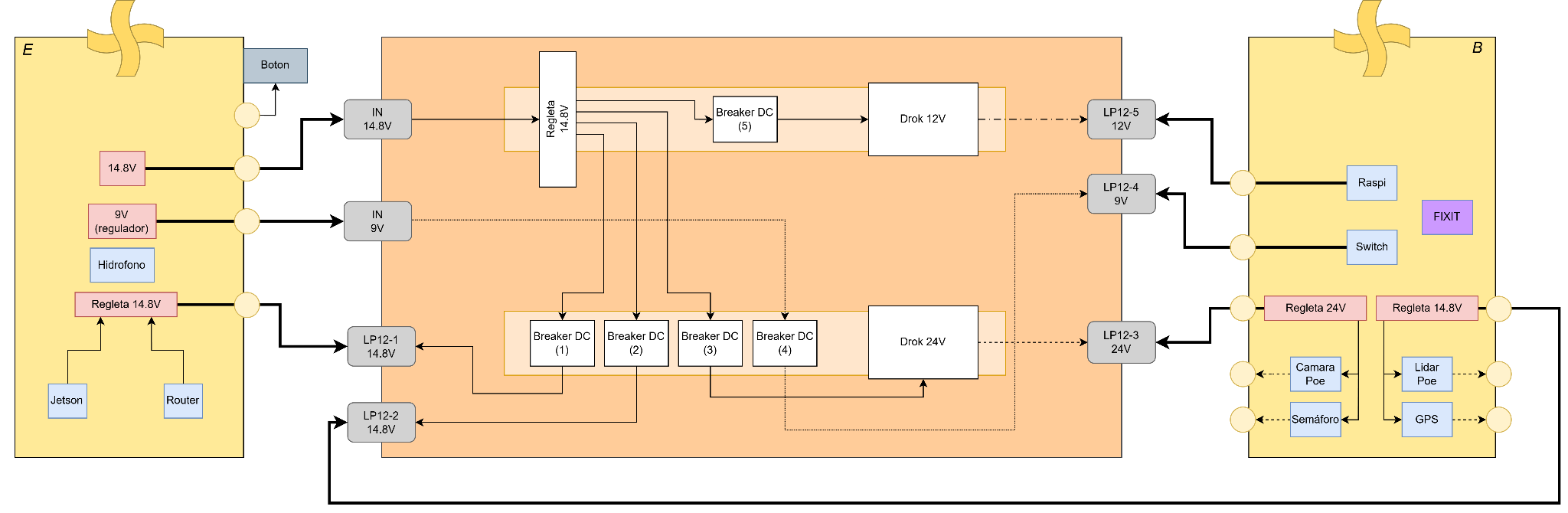
The distribution box receives the nominal 14.8 V line from the starboard float's battery and distributes power to both floats. Its design incorporates terminal blocks, independent DC protections, 12 V and 24 V converters, and LP12 connectors to route outputs to the equipment, along with a 9 V input for the switch. The port side supplies the Jetson, router, and hydrophone, while the starboard side powers the Raspberry Pi, switch, camera, PoE LiDAR, GPS, and status light. The proposed bill of materials includes a Pelican 1200 case, distribution bars, DIN rails, LP12 connectors, and 6 A DC protections, with cable glands at the pass-throughs between the case and the floats and ferrule-terminated conductors on distribution bars inside the BlueBoat, using cables rated for approximately 9 A. Concentrating conversion, distribution, and per-circuit protection in a dedicated enclosure organizes the wiring of both floats and isolates faults by branch.
Power Switch
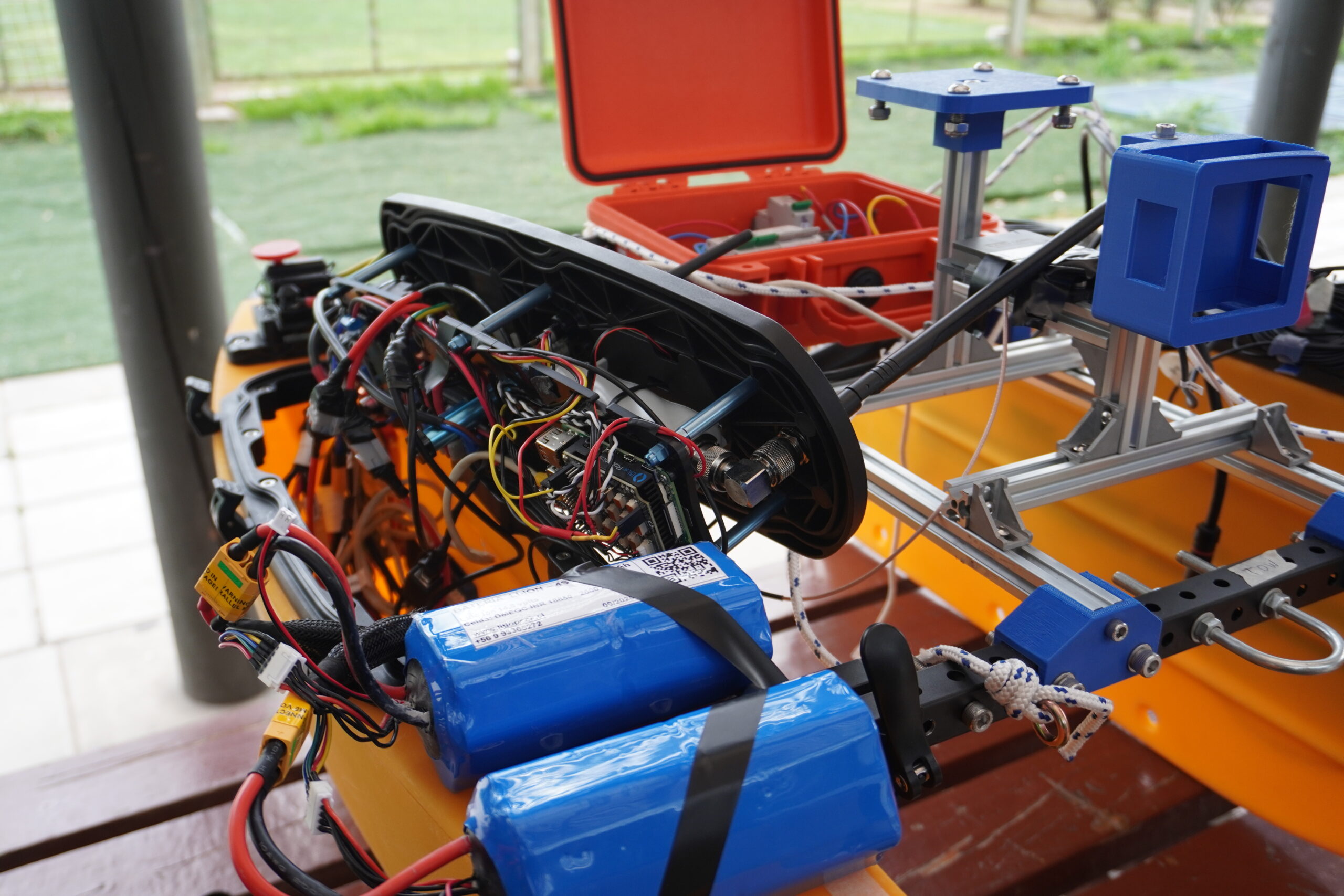
In the BlueBoat's original configuration, the Power Switch connects or disconnects power to the loads via two control terminals and provides a regulated 5V auxiliary output. During testing, a fault was recorded in which the device remained conducting regardless of the control state, with an approximate 0.7V drop between input and output, attributed to conduction through an internal diode, though this has not been confirmed as a definitive diagnosis. Based on this, the component was kept in the actuator branch with the e-stops placed downstream, while computers and sensors are powered directly from the battery distribution. This arrangement confines the observed voltage drop to the actuator branch without affecting the computing equipment. As a result, the starboard Power Switch was omitted from the physical e-stop connection description.